Plugin for Unity to navigate the scene using gestures. Powered by LeapMotion.

Plugin for Unity to navigate the scene using gestures. Powered by LeapMotion.
Want to feel like a wizard? This compelling experience combines visual, audio and haptic stimulation in a supernatural narrative in which the user takes on the role of a wizard apprentice. A wide range of sensations are generated by using different haptic patterns on a novel ultrasonic device by Ultrahaptics.
Winners of an Innovation award in the entertainment category at VR Summit Salzburg
@ultrahaptics #VRWC217 #VRWC2017 thank you and snap @jamiemid the equal youngest! pic.twitter.com/i7BebJeCyl
— Paul Perera ⚫️ (@Pereraps) April 12, 2017
Martinez, J., Griffiths, D., Biscione, V., Georgiou, O., Carter, T. (2018) Touchless Haptic Feedback for Supernatural VR Experiences. IEEE Conference on Virtual Reality and 3D User Interfaces (VR), Reutlingen, pp. 629-630.
doi: 10.1109/VR.2018.8446522 [Web]
Obstetric simulator based on the force feedback device Phantom Premium, created in 2010 and improved in 2011.
This is a Bachelor’s Thesis authored by students Javier Oliver and Manuel Ruiz-Gómez López, supervised by José Pascual Molina and Jonatan Martínez.
The goal of the project is to create a tool to help obstetric students learn the skills to identify the fetus head position and the cervical effacement using haptic technology.
The tool provides a graphical interface to change the parameters of the simulation such as effacement, dilation and hardness.
The device used for this project is a Phantom Premium A. The software uses the H3DAPI libraries.


Tired of having to clear ant set a standard stopwatch every time I wanted to rest during my daily training, I decided it was time to build a custom one. Yeah it would have been easier to download an android app, but you have to unlock the screen every time and, what’s more important, where’s the fun in that?
The objective is clear, measure rest intervals, which are typically 30, 60 or 90 seconds. A graphic progress of the period would be nice to see as well. Having this in mind, I started drawing some drafts.

The one I liked the most is the last one, inspired by the shape of a human eye. Time to think about the electronics!
12 leds need to be controlled, as well as a double 7-digit display, a buzzer and a push button. One cheap way to go here is to use an AT-Tiny85 AVR microcontroller, which has 4 usable digital IO’s. Two of them are used to drive the shift registers, one for the buzzer, and the last one for the push button. I added a 2-pin connector in parallel with the push-button, which can be used for an external trigger (to reset the clock).
The PCB was created using the toner-transfer method, using a hacked laminator.

The component side of the PCB has been painted in black, and mounted with a battery holder. Here is the result.

Note that the ATTiny has been mounted on a socket, so that it can be easily extracted and reprogrammed. The current firmware blinks the led on the bottom every second, and the other leds are turned on every 5 seconds.
Thus, the leds represent fractions of a minute, and the display the number of minutes elapsed since the last reset. Needless to say that the button resets the stopwatch.
Adding an RTC to the design would allow the use of this device to show the time as well, maybe for the next revision.
Here it is a video of the clock in action. As required, it beeps at 30, 60 and 90 seconds, and then it keeps counting quietly.
I used to make my own circuits with the toner transfer method. However, it has a lot of drawbacks, especially for SMD components with fine pitch. The first step to high resolution PCBs is building my own ultraviolet exposure box.
Instead of using UV tubes, I’ve made an array of UV leds. They are cheaper, more durable and energy efficient. These are the features:
– exposure area of 18×24 cm
– 2 boards of 54 leds each, in 6×9 configuration. 108 leds in total.
– 2 cm of separation between each pair of leds, 7 cm between the leds and the PCB.
– twin led array configuration for a white light box (to align transparencies).
– exposure time: not critical, 6 to 11 minutes
The measured forward voltage of the leds is 3.27 volts. They are configured in series of 3 leds with a resistor of 120 ohms, which gives a current of 18.5 mA when using a 12 volts power supply.
The PCBs for the led matrix has been made with the toner transfer method. The huge size of the boards used (180×120 mm) cools down the laminator and the toner didn’t stick well to the copper, so I had to use a pen marker. This is one of the reasons I’m going for the UV exposure method.
Note that there are in fact two circuits in the board. One is for the UV leds and the other is for the white leds (which I haven’t received yet). Thus, half of the holes will remain unpopulated for the moment.
![]()
After soldering the resistors and the leds, I filed and sanded them flat to help diffusing the light emitted (originally at 20º). A pair of marker pens were cut and placed at the sides of the two PCBs in order to hold them together. It’s a fast and clean way to keep them in position while I receive the white leds.

I put the circuit inside an old scanner, and tested the leds for dead units. Note the old halogen lamp which will be removed as soon as I get the white leds.

I used a translucid plastic sleeve as a light diffuser.

And this is the light pattern, pretty homogeneous in my opinion.

A lot of parameters are involved in the ideal exposure time of a specific photosensitized board: number of leds, distance to the leds, etc. Having other exposure box as a referenced, I estimated the times to be between 3 and 10 minutes. To find the best time of my setup, I designed a board with traces from 0.01′ width (0.254 mm) to 0.05′ (1.270 mm) and clearing spaces from 0.254′ to 0.635′. The circuit was replicated four times, so that each one of them could be exposed to UV for a different period of time (3, 6, 9 and 11 minutes).
I printed the four identical circuits two times in a transparency with a laser printer, and folded them together to get deeper blacks.
![]()
This was the result after revealing the PCB.

Three of them seem to be very similar, which were exposed to 6, 9 and 11 minutes of UV ligth. The darkest one was exposed 3 minutes. Let’s go and etch them.

I was surprised of the high resolution achieved. The results are fairly consistent despite the different exposure times used. The least exposed one (botton-left) needed a longer etching process, but I stopped it to avoid damaging the others. Here is the result after cleaning the PCB.

This is the detail of the 9 minutes one:

And these are the thinnest tracks seen under the microscope.
Still room for even thinner traces in my opinion!
Update:
The project files have been uploaded to Github.
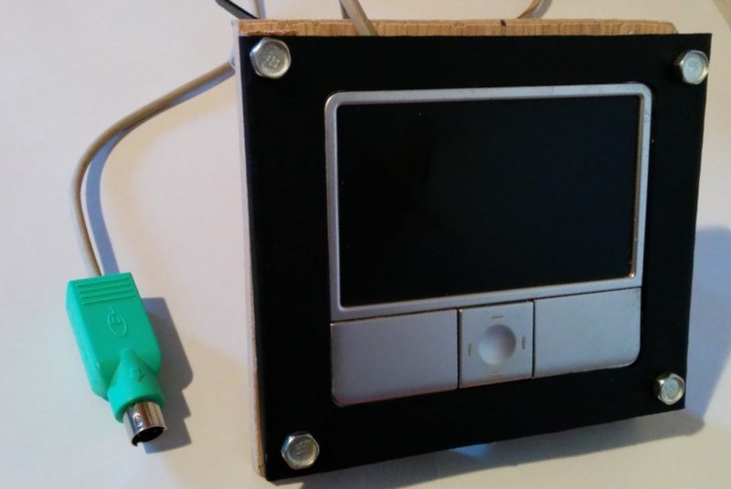
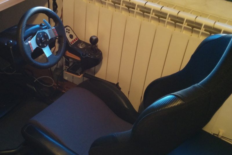
When using a driving cockpit for simulators like rFactor 2, a pointing device is mandatory to interact with the user interface. Not only it is necessary to move from one menu to other, but also to adjust the car and race settings. Some cockpits include a custom tray and a mouse, but it requires a lot of space around the seat that is not always available. In my case, I used to have a wireless mouse on top of a chair.
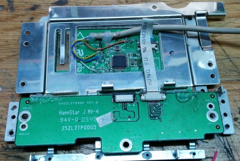
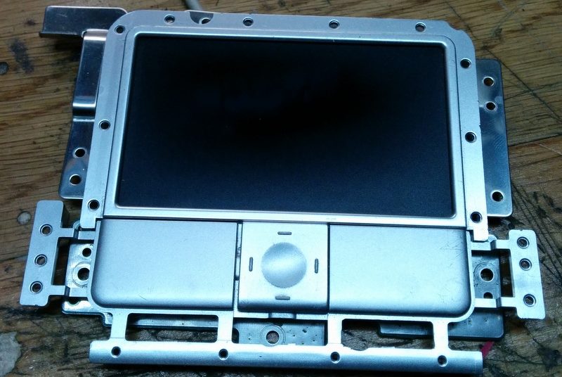
To solve this, I have repurposed an old touchpad from an Acer Aspire 1690. The model of the chip is Synaptics T1006 0544, and it uses a PS/2 serial communication to the computer. As the laptop uses a custom connector, all we have to do is to find the datasheet of the controller and wire it appropriately.
I found the schematic on this blog. The pinout of interest of the chip is:
| Pin no. in chip | Description | Pin in PS/2 conn. |
| 2 | Data | 1 |
| 3 | Clock | 5 |
| 43 | VCC | 4 |
| 45 | Ground | 3 |
Pin number one of the chip is marked with a circle, and following pins are numbered counter-clockwise. The pinout of a regular PS/2 mouse connector can be found here. To solder the wires, I traced the pins and used the testpoints of the board.
For modern computers, a PS/2 to USB adapter (can be found easily on ebay) is convenient.
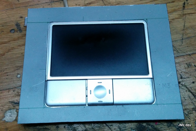
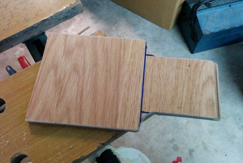
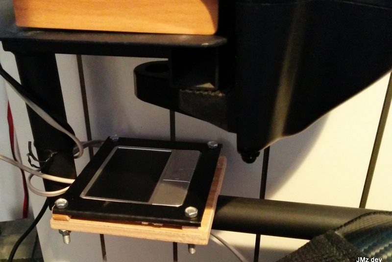
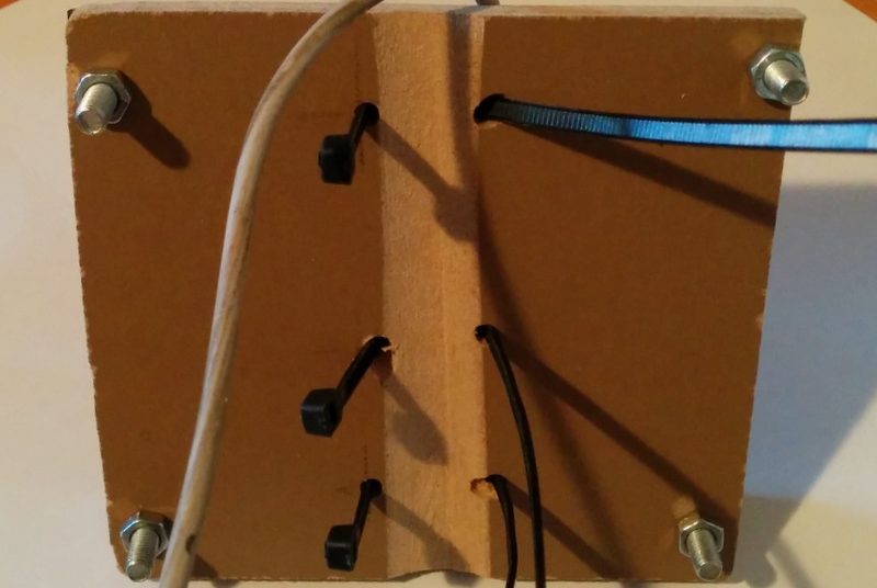
Next thing to do is to make a frame and a support for the cockpit. Back then I didn’t have a 3D printer, so I made mine with a thin sheet of metal and wood.
This video shows an early test I did in 2013 motivated by Johnny Chung Lee and his Wii Remote head tracking. While he uses a Wii Remote to perform the tracking, I used a PhaseSpace active optical tracking system we have at the university.
I developed the software using the great Ogre3D rendering engine.
In the first part of the video I only track the head (with one marker).
In the second part I also track the monitor (with three markers, to track rotation as well).
Development of a vibrotactile dataglove composed of 11 ERM actuators in an experiment to identify 3D shape, sizes and weights.
These experiments demonstrate the feasability of using the vibrotactile technology to carry out complex tasks, such as 3D shape, size and weight identification without visual guidance. The vibrotactile glove was built using the Vitaki Toolkit, with 11 ERM actuators attached to the fabric. It uses the PhaseSpace Impulsesystem to capture the motion, along with an inverse kinematics algorithm to calculate the skeleton and the position of the actuators in space.

Level of activation of the vibrotactile actuators when touching a cone
Video conference system based on multiple cameras and face tracking to provide a 3D effect using motion parallax. This is a Bachelor’s Thesis authored by Miguel Ángel Muñoz and supervised by José Pascual Molina and Jonatan Martínez.
Video conference systems have evolved little regarding 3D vision. An exception is where it is necessary to use special glasses for viewing 3D video. This work is based primarily on the signal of vision motion parallax. Motion parallax consists in harnessing the motion of the observer, and offering a different view of the observed environment depending on his/her position to get some 3D feeling. Based on this idea, a client-server system has been developed to create a video conference system. On the client side, a camera that sends images to the server is used. The server processes the images to capture user movement from detecting the position of the face. Depending on this position, an image is composed using multiple cameras available on the server side. Thanks to this image composition, and depending on the user standpoint, 3D feeling is achieved. Importantly, the 3D effect is experienced without the use of glasses or special screens. Further, various composition models or change modes between cameras have been included to analyze which of them achieves a greater improvement of the 3D effect.
Muñoz, M. A., Martínez, J., Molina, J. P., González, P., & Fernádez-Caballero, A. (2013). Evaluation of a 3D Video Conference System Based on Multi-camera Motion Parallax. In 5th International Work-Conference on the Interplay Between Natural and Artificial Computation, IWINAC 2013 (pp. 159-168). Mallorca, Spain. [Web]
This system consists of a Virtual Reality setup to model 3D objects with the hand, and it provides vibrotactile feedback to the user.
The main features of the system are:
Bachelor’s thesis (spanish) [PDF]
Presentation (spanish) [PDF]
Martinez, J., Molina, J.P., Diseño y construcción de un sistema inmersivo y de un guante con retorno táctil para el modelado de objetos 3D con las manos. Bachelor’s thesis, University of Castilla-La Mancha, 2007.